8-BIT BREADBOARD COMPUTER

Overview
This is my modified build of Ben Eater’s 8-bit CPU project, which is an incredible introduction to digital electronics and computer architecture! I won’t explain the background to the project in detail here, so do check out Ben’s comprehensive introduction.
In brief, the idea is to use basic 7400-series logic chips wired together on breadboards to build the simplest possible programmable computer from scratch.
The architecture and layout of my build follows Ben’s fairly closely, with a few enhancements:
- 74HC series chips
- 16-bit address bus, to enable addressing of 32KB SRAM
- 16-bit memory address register
- 16-bit instruction register, to give an 8-bit instruction opcode and 8-bit operand
- 2 x 16-bit general purpose registers C and D, although arithmetic remains 8-bit
- 8-bit segment register to extend the 8-bit program counter (allowing execution beyond the bottom 256-byte memory segment)
- Arduino Nano to bootstrap the SRAM, and allow direct SRAM writing via USB
Code
Code for the various components described below is available on my GitHub.
Architecture
The layout of the CPU modules is as follows, with the 16-bit bus running through the centre.

Control Lines & Instruction Set
The following is a snippet of the declarative specification for the control lines and instruction set (opcodes and microcode), which is converted and written to the control EEPROMs.

We have 24 control lines (hence 3 control EEPROMs with 8 outputs each), each of which enable the function of one thing. For example, the ‘AIN’ line instructs the A register to load from the bus, the ‘PCEN’ line instructs the Program Counter to increment, etc.
Each instruction has 8 microcode steps, each step being a combination of enabled control lines.
The instruction set consists of:
- NOP
- HALT
- Load Reg from Memory Address
- Load Reg from Immediate
- Store Reg to Memory Address Direct/Indirect
- Jump to Memory Address Direct/Indirect
- Jump if Carry Flag
- Jump if Zero Flag
- ALU Add
- ALU Subtract
- Output DL to Display
Assembly Language
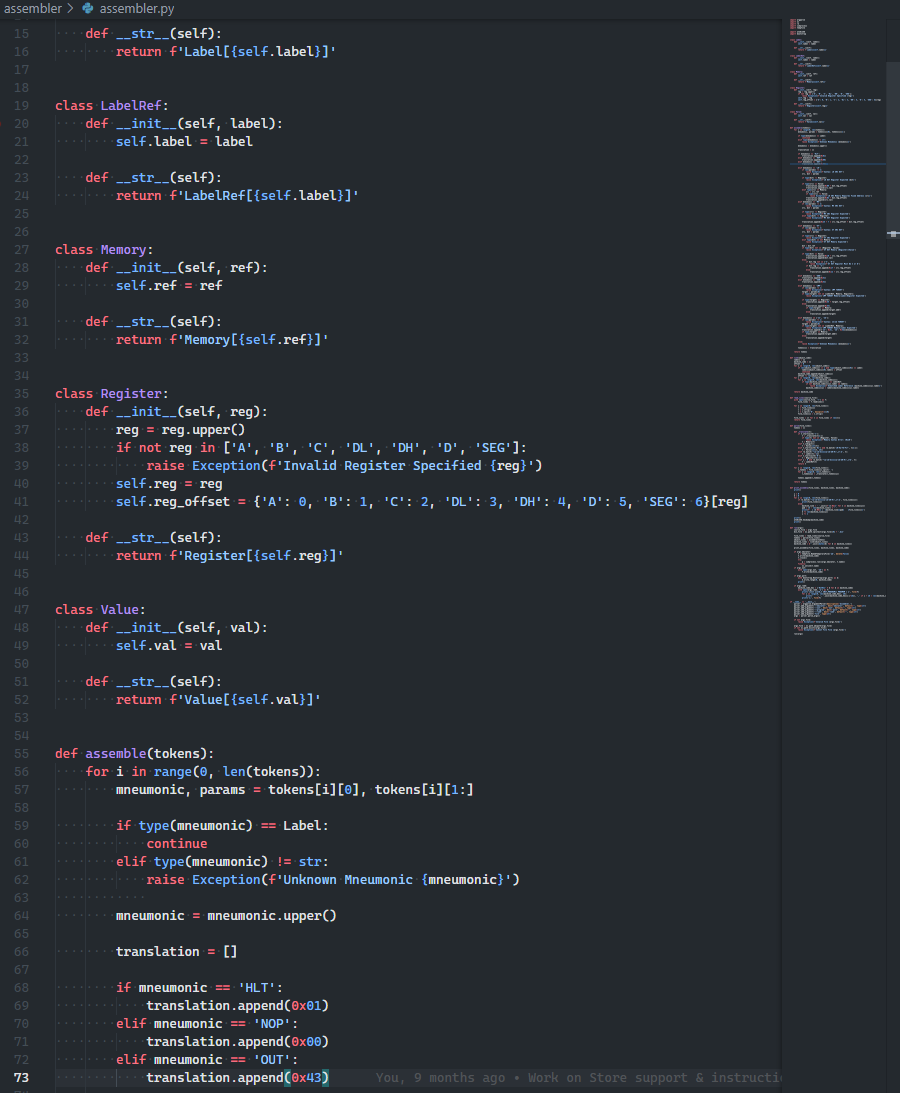
I implemented a simple assembler to convert an assembly language into machine code for the computer. The following is an example of an assembly program to brute-force prime numbers below 255 (with a rough Python translation at the top):
# Equivalent Python:
#
# for a in range(2, 256):
#     d = 0
#     for b in range(2, a):
#         c = a
#         while c > 0:
#             c = c - b
#             if c == 0:
#                 d += 1
#     if d == 0:
#         print(a, 'prime')

reset:
    LD 0x01 RA   # Intel-like syntax: load immediate 0x01 into A
    ST RA *0xff  # Store value in A into memory location 0xff

next_candidate:
    LD *0xff RA
    LD 0x01 RB
    ADD
    JC reset
    ST RA *0xff
    LD 0x01 RB
    ST RB *0xfe
    LD 0x00 RD

next_trial:
    LD *0xfe RA
    LD 0x1 RB
    ADD
    ST RA *0xfe

    LD *0xff RA
    LD *0xfe RB
    SUB
    JZ found_prime

    LD *0xff RA
    LD 0x00 RC

test_loop:
    SUB
    JZ next_candidate
    JC test_loop # SUB A B => CF set if A >= B, not A < B
    JMP next_trial

found_prime:
    LD *0xff RA
    OUT
    jmp next_candidate

It simply tokenises an input assembly language file, and converts each mneumonic and (optional) operand into opcode byte and parameter byte.
Emulator
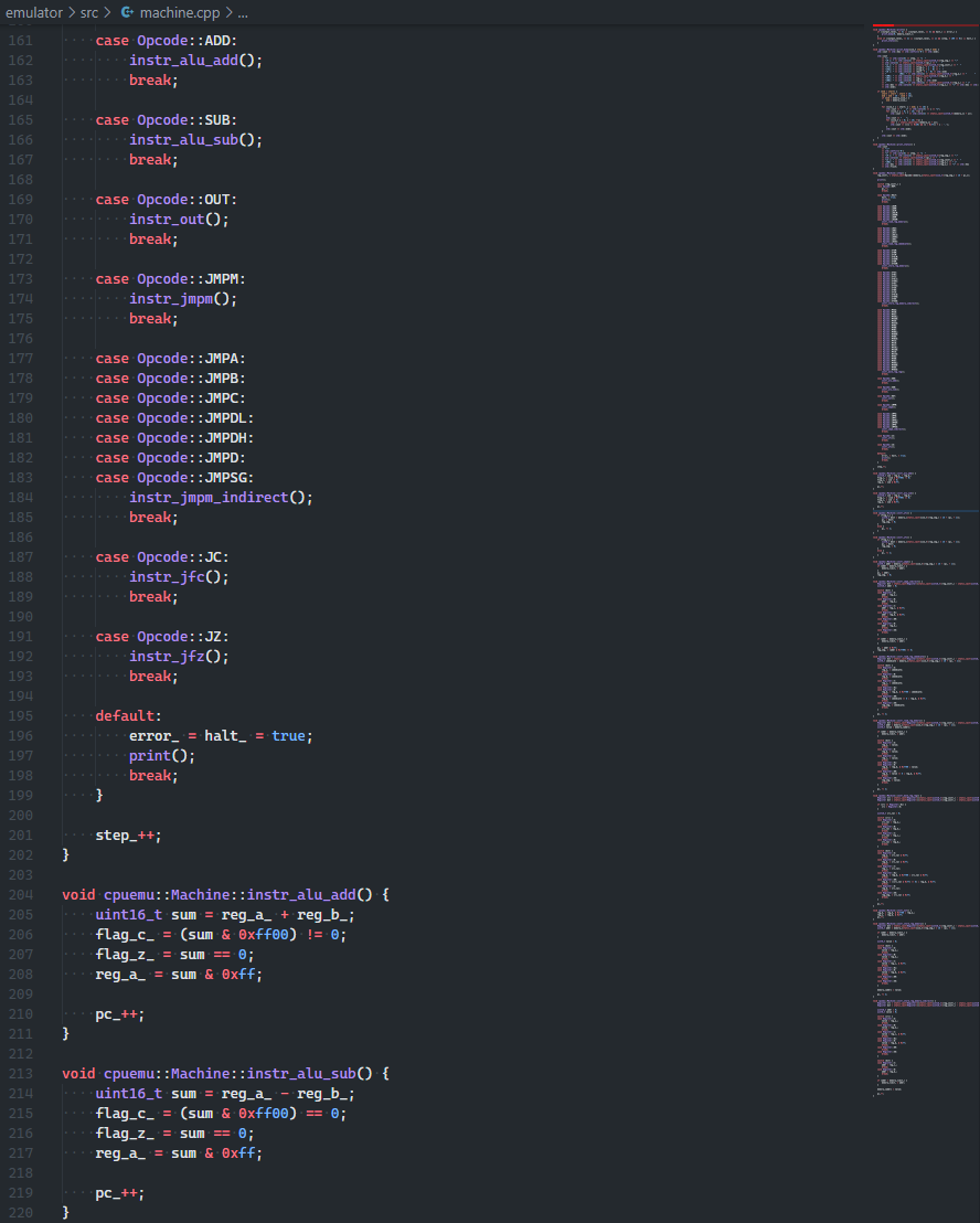
I also wrote an emulator in C++ to ease program development - far quicker to test locally than storing, resetting and running on the actual board!

This is a snippet of the main loop with opcode switch and two ALU instruction handlers.
Assembling & Emulating

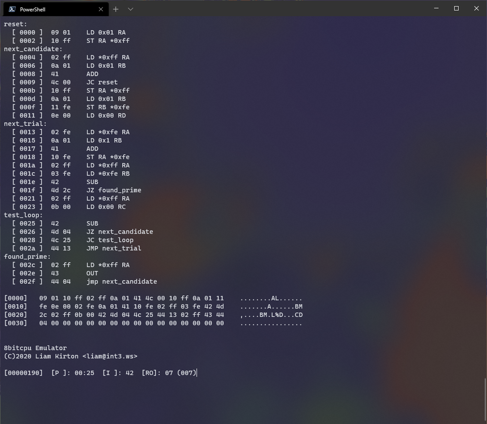
Here we’ve assembled the prime-test program above, and piped it through into the emulator.
We can see that the emulated computer is executing the instruction at address 0x25, with opcode 0x42, corresponding to a SUB.
In total, the emulated computer has executed 0x190 (400) instructions.
The output register currently displays 7.